| Utilization |
Production |
Production |
Production |
R&D, Production |
R&D, Production |
Production
Measurement in batches |
R&D |
| Sample type |
Flat |
Flat |
Spherical |
Flat
Spherical |
Flat
Spherical
Toric
Aspheric
Cylindrical |
Spherical
Toric
Aspheric |
Flat
Spherical
Toric
Aspheric
Cylindrical |
| Sample size (measurement range) |
Different versions
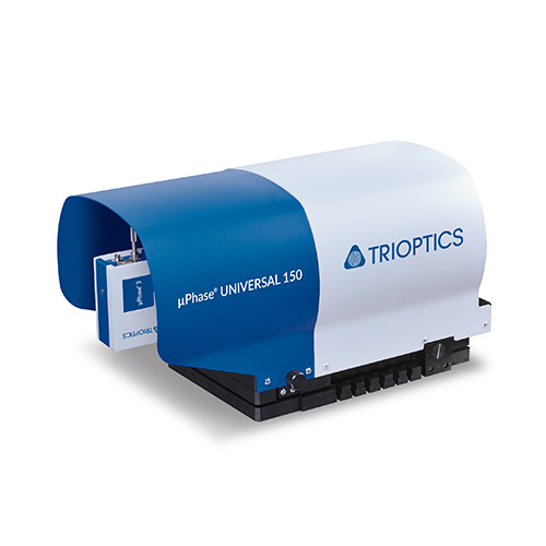
up to max. Ø 150 mm |
Different versions
up to max. Ø 150 mm |
Sample size depending on measurement objective
(Measurement objective as link to the overview from the brochure page 16 + 17 |
Max. Ø50 mm
Sample size depending on version and test lens
(Measurement objective as link to the overview from the brochure page 16 + 17) |
Max. Ø 100 mm
Sample size depending on measurement objective
(Measurement objective as link to the overview from the brochure page 16 + 17) |
Ideal for small diameters |
Max. Ø 150 mm
Sample size depending on version and test lens
(Measurement objective as link to the overview from the brochure page 16 + 17) |
| Max. sample weight |
5 kg |
1.5 kg
(depending onconfiguration) |
1.5 kg
(depending on configuration) |
1.5 kg |
1.5 kg |
1.5 kg |
1.5 kg |
| Alignment tools |
Manual tilt |
Manual tilt |
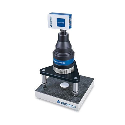
Manual XY adjustment, tilt table and z-focusing (a few mm) |
Manual XY adjustment,
tilt table and Z-focusing |
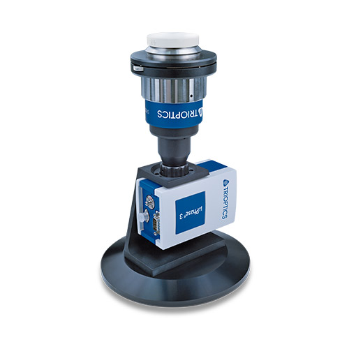
Manual tilt table
Manual XY table
Motorized, computer-controlled Z-axis |
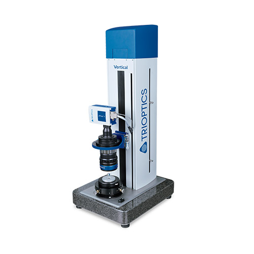
Motorized, computer-controlled X/Y/Z-axis |
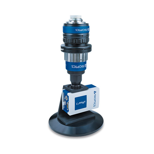
Manual tilt table
Manual XY table
Manual Z-axis |
| Test range radii measurement |
Not available |
Not available |
Typically 10 mm ... 200 mm
Relative radius measurement compared to a radius normal, range depends on test objective and
holder |
Approx. 220 mm
Absolute radius measurement with gauge (analog or digital) |
Approx. 300 mm
Integrated, automated absolute radius measurement |
Max. 50 mm
Integrated, automated absolute radius measurement |
Up to 2 m, depending on test objective and length of the radii measuring rail
Integrated absolute radius measurement
especially for long radii |
| Accuracy radius measurement |
- |
- |
Depends on the accuracy of the radius normal |
Depends on gauge:
0,5-5 µm |
Depends on gauge:
0,1-5 µm |
±0.1 µm |
30 µm |
Dimensions
(h x w x d) |
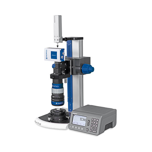
Base:
S: 300 x 300 mm² (free working distance 180 x 180 mm²)
L: 440 x 440 mm² (free working distance 330 x 330 mm²)
Free working height : 110 mm / 155 mm / 200 mm |
500 x 200 x 200 mm³ |
500 x 200 x 200 mm³ |
500 x 300 x 400 mm³
moving range between 160-300 mm (depends on configuration) |
830 x 350 x 420 mm³ |
350 x 530 x 750 mm³ |
500 x 2500 x 400 mm³ (width depends on length of the rail) |
| Weight |
S: 25 kg L: 45 kg |
5 kg ... 20 kg (depends on configuration) |
5 kg ... 20 kg (depends on configuration) |
20 kg |
55 kg |
100 kg |
30 kg (depends on configuration) |
| Type |
Table top device |
Table top device |
Table top device |
Table top device |
Table top device |
Table top device |
Table top device |
| Options |
Transmission measurement |
|
|
|
CGH bracket for measurements of aspheres, cylinder or toric surfaces
MTF measurements
Transmission measurement |
|
CGH bracket for measurements of aspheres, cylinder or toric surfaces
MTF measurements
Transmission measurement |

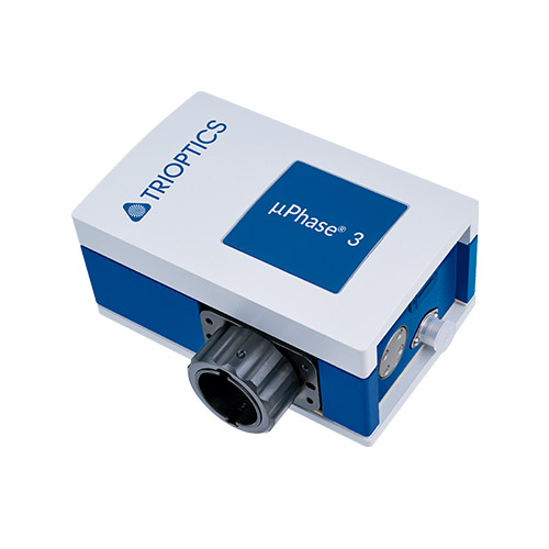


 Download Technical Data µPhase®


 Twyman-Green construction
 Fizeau construction